What is Intrinsic Safety?
Intrinsic Safety is one of the several protection techniques used in hazardous areas. This type of protection is applicable to electrical apparatus in which the electrical circuits themselves are incapable of causing an explosion in the surrounding explosive atmospheres. This short Intrinsic Safety design guide will give you an idea of how Intrinsic Safety is used in hazardous areas.
What are Hazardous Areas?
Hazardous Areas are those parts of a plant or facility that have a higher probability of explosions or fire, due to the nature of the materials handled, processed or stored there. Examples of places that have hazardous areas include underground mines, coal handling plants, Oil and Gas facilities, chemical manufacturing plants, chemical warehouses that store explosive or flammable materials and even places like sugar factories (where sugar dust explosions could take place). In order to prevent disasters due to explosions or fires in hazardous areas, these areas are classified according to the risk that they pose. This is known as Hazardous Area Classification.
So for example, a Class 1, Division 1 area has a higher likelihood of having an explosion, than a Class 1 Division 2 area. The Division concept comes from NEC standards used in North America.
In the rest of the world, IEC and ATEX Zone concepts are uaed to classify hazardous areas. Here is a guide to understand Ex-Zones.
Hazardous Area Equipment needs to be explosion protected
Equipment used in hazardous areas (all equipment, not just electrical equipment) should be such that the use of the equipment does not become the cause of an explosion. Hence special types of explosion protection techniques are used when manufacturing such equipment. There are many such techniques including explosionproof, flameproof, intrinsic safety, pressurization, increased safety and so on.
Intrinsic Safety meaning
Intrinsic Safety means that the equipment is intrinsically safe and will not be the cause of an explosion, if used in hazardous areas. Intrinsically safe electrical equipment has to be necessarily a low voltage, low energy type of equipment such as measuring equipment like pressure transmitters, switches, LED lamps, flashlights and even some types of specially designed radios and mobile phones, tablets and displays.
Intrinsically safe circuits do not give off enough energy to ignite a flammable mixture of gas/vapors and air in hazardous areas. The Intrinsic Safety symbol used is Ex-i (with variations of Ex-ia, Ex-ib and Ex-ic based on the number of faults that it is protected against).
Intrinsic Safety Design Guide
Here is a short intrinsic safety circuit design guide.
Among Intrinsic Safety standards, the International Standard IEC 60079 deals with hazardous areas. Part IEC 60079-11 deals with Intrinsic Safety design. as well as with other aspects including Intrinsic safety levels of protection, apparatus construction, ignition compliance, labels and markings, infallible components, and testing.
An Intrinsically safe loop consists of a field instrument or device that is located in the hazardous area (such as a transmitter or a switch), a safety barrier that routes power and signals to the field device from the marshaling panel or control room, and the control room device (which could be a receiver instrument such as a single loop controller, or an Input/Output card of a DCS or PLC).
Thus there are mainly three parts of an IS loop. A simple non-IS loop has only two parts as below:
1. The field device such as a transmitter
2. The Receiver Instrument in the control room (could be an I/O card channel of a PLC or DCS).
A basic IS loop has an additional device in between the two, which is known as an Intrinsically Safe barrier. Thus a basic IS loop has the following three components:
1. The field device such as a transmitter
2.A safety barrier
3. The Receiver Instrument
Additionally the cable used to interconnect this is also important and should not be of a type that can store energy. It has specific requirements, such as the cable L/R ratio, which is the ratio of the Cable Inductance to Resistance. A good IS cable has its L/R ratio of about 40 or less.
What is the function of the safety barrier?
The barrier ensures that
a) Faults from the control room side are not carried over to the field side (which is located in a hazardous area)
b) Faults in the IS circuit, including occurring in the hazardous area side are handled without causing any sparking in the hazardous area.
Zener Barriers and Galvanic Isolators
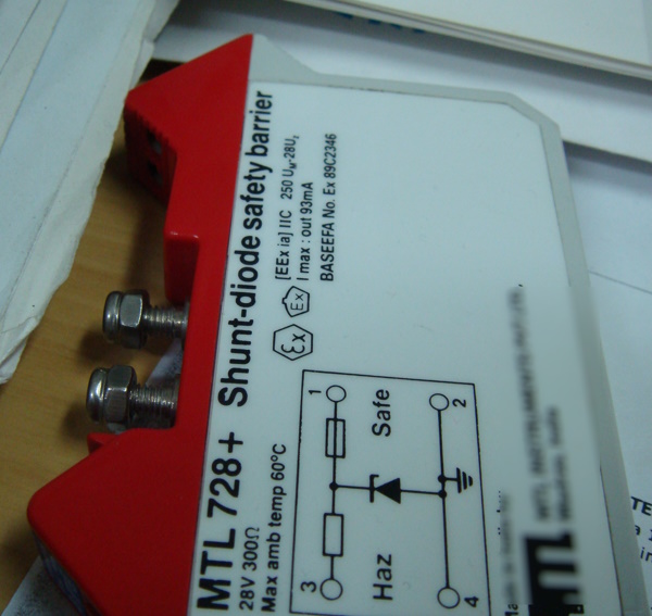
The Intrinsic Safety barrier used can be a Zener Barrier (that uses Zener diodes) or could be a Galvanic Isolator (that provides galvanic isolation between the field and the hazardous area).
Selection, engineering and design of the Intrinsically Safe loop is very important to ensure that the Intrinsic Safety design works well without causing an explosion. This responsibility is of the Instrumentation Engineer who designs the loop. It is not the same as using explosionproof or flameproof instruments, where one can simply use an explosionproof or flameproof transmitter and connect it via conduits or armored cables having suitable cable glands, to the control room. In an IS loop the entire loop, including the devices, barriers, control room equipment and cables should be matched to each other to ensure that the loop is Intrinsically Safe.
How to do this?
Take the Abhisam Intrinsic Safety training Course today to learn how to do this. The course consists of text, voice, animations, simulations, real life examples to help you understand how to design an Intrinsically safe loop.


